Over the holiday season I started looking at whether my boiler, a Worcester Bosch Greenstar 28i, was compatible with the Nest thermostat. After some Googling I began to wonder whether I could make my own controller and began investigating how the existing wireless programmer might function. The programmer currently in use is a British Gas WR1, which looks to be a re-branded Drayton Digistat device.
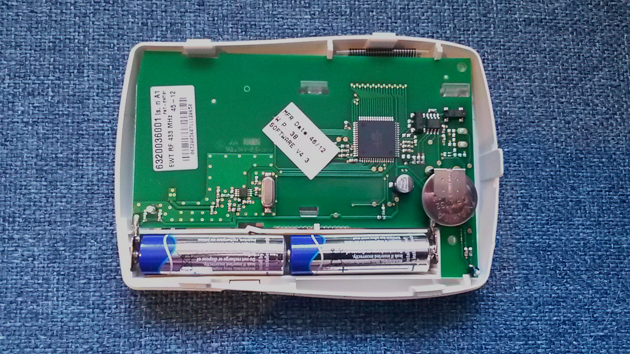
After removing the programmer from its wall mounting plate I immediately noticed a sticker indicating it operated using 433MHz. Thankfully this is part of the unlicensed spectrum meaning transmitters are likely to be readily available. Sure enough, there are 433MHz transmitter/receiver pairs available in the UK for just £2 on eBay. I immediately bought myself an Arduino, some cables, a breadboard and waited eagerly for everything to arrive.
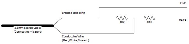
My plan was to create a single channel logic analyser as described in Steven Hale’s excellent blog post, using the soundcard in my laptop to capture what my existing programmer transmits. My soldering ability leaves a lot to be desired, so I’ll spare you a photo and include a diagram that is likely to be much more useful:
With my logic analyser built I then proceeded to install Audacity and begin trying to record the data sent by my wireless programmer. I started recording and turned up the heating, it was immediately apparent that something had recorded as once transmission completed there was a 100ms radio silence:
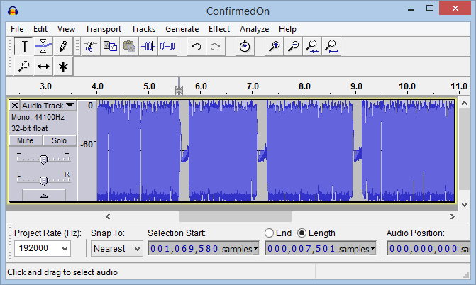
According to the Steven Hale, the same person who provided the details for creating the logic analyser, these little 433MHz radios have gain control – once they detect nothing they try to boost the signal which is why we get the 100ms radio silence and then noise. If you try to reproduce this recording, you are looking for three repeats of the same transmission. Since the wireless programmer has no receive capability it must blindly transmit and hope for the best, so it does this three times.
To make things a bit easier it’s best to set Audacity to use 192KHz sampling (bottom right, set “project rate”). You’ll also want to view the track as a waveform (click the down arrow by the words “Audio track” and select “Waveform (dB)”.
Zooming in yet further I could finally see the transmission data:
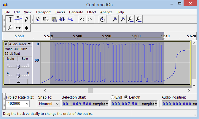
The next step was to count the number of samples to determine how long I needed my radio to transmit for, requiring yet more zooming.
in and selecting a portion of the on/off state. I counted the number of samples and repeated this until the 100ms of radio silence at the end:
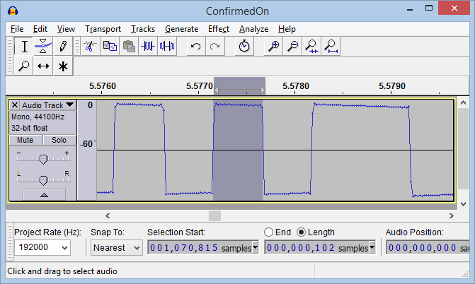
I then multiplied these values by 5.2083333 to get the number of microseconds (μs). I ended up with 60 values for “heating on” and 62 values for “heating off”. The next step was then to wire up the 433MHz transmitter I bought from eBay to my Arduino and try and reproduce these signals.
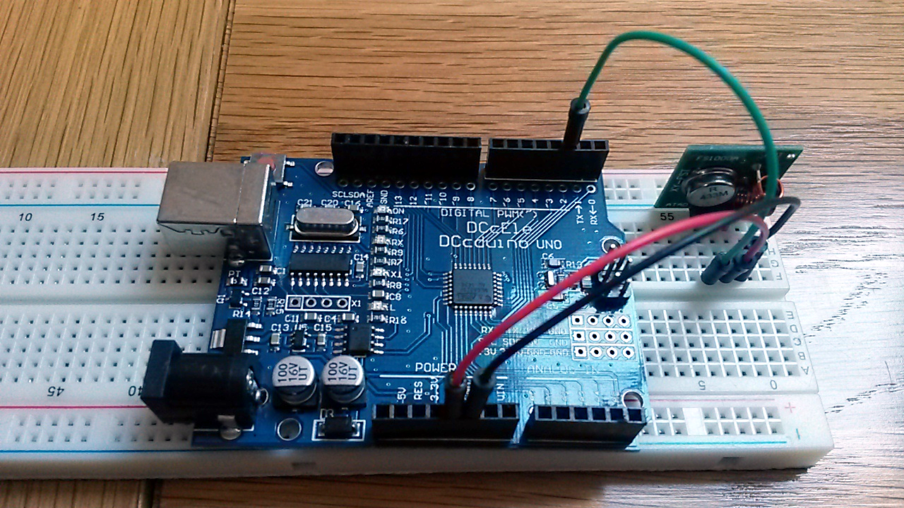
I ran some code I wrote in the days leading up to delivery and to my surprise it worked first time, a sample version of this can be found below.
const uint16_t arrOn[] = {
  632, 491, 0,0,0,0 // Put the values you recorded here.
};
const int nOnLen = sizeof(Heating::arrOn)/sizeof(int);
const uint16_t arrOff[] = {
  1599, 521, 0,0,0,0 // Put the values you recorded here.
};
const int nOffLen = sizeof(Heating::arrOff)/sizeof(int);
const int nTxPin = 2; // Arduino digital pin you're using for radio data.


/**
* Transmits a signal on the specified PIN according to a pattern described by
* the start[] array.
* @param start[] Array in on/off pairs for how long in microseconds to
* transmit and then wait for. N.B. Microsecond is 1/1,000,000 of a second.
* @param arrLen Lengh of the array - usually sizeof(array)/sizeof(int).
* @param txPin Digital pin the transmitter data pin is connected to.
*/
void transmitArray(const uint16_t start[], int arrLen, int txPin)
{
  // Loop over objects in an array.
  for(int i = 0; i < arrLen; i = i + 2)
  {
    // Turn on the transmitter
    bitWrite(PORTD, txPin, 1);

    // Wait (transmitting) for the duration specified.
    delayMicroseconds(start[i]);

    // Turn of off the transmitter.
    bitWrite(PORTD, txPin, 0);

    // Wait (not transmitting) for the duration specified.
    delayMicroseconds(start[i+1]);
  }
}


/**
 * The setup() function is called when a sketch starts. Used  to initialize
 * variables, pin modes, start using libraries, etc. The setup function will
 * only run once, after each powerup or reset of the Arduino board.
 */
void setup()
{
  pinMode(nTxPin, OUTPUT);

  Serial.begin(9600);
  Serial.println("Press 0 to turn off heating");
  Serial.println("Press 1 to turn on heating");

}


/**
 * The loop() function loops consecutively, allowing the program to change and
 * respond. Used to actively control the Arduino board.
 */
void loop()
{
  if (Serial.available() > 0)
  {
    int nIncomming = Serial.read();
    if (nIncomming == 49) // char code for 1
      transmitArray(arrOn, nOnLen, nTxPin);

    if (nIncomming == 48) // char code for 0
      transmitArray(arrOff, nOffLen, nTxPin);
  }
}
Pressing 0 turns off the heating and 1 will turn it on.